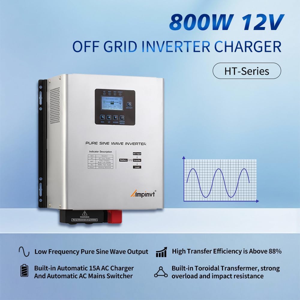
Getting the AMPINVT HT-800W12V UPS/inverter talking to Home Assistant requires tapping into its RS485 Modbus port using an ESP32 and ESPHome. After mapping the registers and working through some hardware quirks, the full configuration is available in my ampinvt-ht800w12v-esphome repository.
The architecture is straightforward but relies on a specific physical data path.
- The inverter connects via an RJ45 cable to a HiLetgo TTL-RS485 UART module, which passes the data to an ESP32 running ESPHome.
- ESPHome handles the Modbus polling every 5 seconds and pushes the metrics directly to Home Assistant using the native API, bypassing the need for an MQTT broker.
- Once configured, Home Assistant automatically discovers the ESP32 on the network via mDNS.
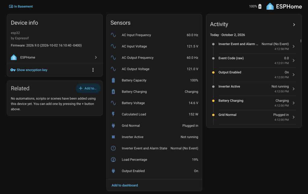
My device view in Home Assistant:
Wiring the RJ45 port requires some precision, but its straightforward. The data lines are on pin 1 (A+), pin 2 (B?), and pin 8 (GND). It is critical to leave pin 6 disconnected, as it carries roughly 18.5V and will instantly destroy the RS485 transceiver. When connecting the HiLetgo module to the ESP32, standard UART conventions failed completely. Every poll timed out until I realized this specific auto-flow-control module required straight wiring – module TXD to GPIO17 and RXD to GPIO16 – rather than the standard crossover.
The link layer itself matched upstream reverse-engineering efforts: 9600 baud, 8N1, slave address 1, Modbus RTU, and CRC-16. However, the register mapping on the 800W unit required significant testing and cross-referencing with a translated 2018 protocol document from the manufacturer, Foshan Jinguangyuan Power Technology Co (original + translated copies in my repo).
- Register 6 initially looked like it was reporting charge current, but testing with a ~95W box fan confirmed it is actually reporting the raw Load Percentage.
- Registers 4 (Output Current), 13 (Internal Temperature), and 14 (Ambient Temperature) are fully documented in the vendor spec but are unimplemented on this specific 800W model, returning static zeroes regardless of physical conditions.
- Because the unit does not report actual output wattage, ESPHome calculates an estimated power draw using the formula
load_percentage × 8.0based on the unit’s 800W rating. - The Operating Status Word (Register 32) tracks exact operational states. I verified this bitfield by physically cutting the grid input, which successfully triggered the transitions between Grid Normal, Battery Charging, and Inverter Active states as expected.
The ESPHome YAML file handles all the math and bit-level decoding directly on the microcontroller, meaning no custom YAML is required on the Home Assistant side. If you are integrating an AMPINVT unit, grab the code from the repo and double-check your TX/RX pairs if your logs stay quiet.
Overall I’m happy with this 800w UPS / Inverter, as you can tell from the Home Assistant device view, I have a 12v LifePo4 100ah battery setup and it works great for an average workload of 200w running my Homelab and Unifi network (with PoE cameras).